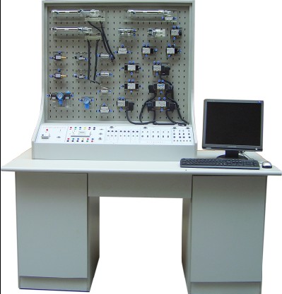
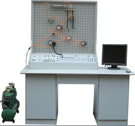
Pneumatic PLC control laboratory equipment hydraulic PLC control test-bed
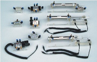


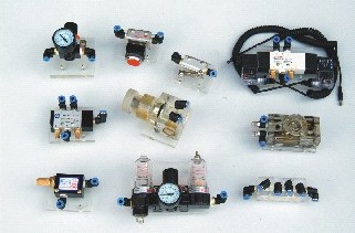


Transparent hydraulic transmission Demonstration System
Pneumatic integrated PLC control laboratory equipment
Hydraulic integrated PLC control laboratory equipment
Pneumatic Hydraulic integrated PLC control laboratory equipment
Pneumatic integrated PLC control laboratory equipment
Hydraulic integrated PLC control laboratory equipment
Pneumatic Hydraulic integrated PLC control laboratory equipment
PLC control laboratory is based on "Hydraulic and Pneumatic Drive," "pneumatic control technology" GM materials requirements, the recommendations of the teachers and students of reference, well-designed form. The system can be carried out in addition to basic conventional pneumatic control circuit experiment can be extended to simulate experimental application of pneumatic control technology, pneumatic technology curriculum design, and programmable logic controller (PLC) and its basic application of experimental study, electromechanical the Perfect Combination of typical laboratory equipment.
The system adapted to colleges, vocational schools mechanical engineering, mechanical and electrical integration, the creation of automation professionals, "Hydraulic and Pneumatic Drive," "pneumatic control technology", "PLC Programmable Logic Controller Theory and Application", and other related courses teaching experiment, but also as a machine, electricity, gas, an integrated test-bed.
Students through practical experiments and curriculum design, can be accurate, image, in-depth understanding of the structure of master pneumatic components, pneumatic control circuit theory and design methods. Also
Through experiments, master PLC programmable logic controller functions, control theory and programming skills.


Note: scalable type for computer networking, multi-laboratory experimental device through the network, each experimental device sent to the experimental data processing computer, teachers can restore through computer simulation experiments students of the true results of experimental efficiency can be greatly improved .
Pneumatic PLC control laboratory equipment
Pneumatic PLC control laboratory main features:
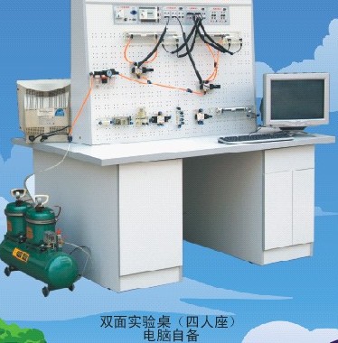
1, the experimental system uses "Combo" structure, an experiment that is equipped with two sets of experimental equipment table for the two groups to conduct experiments on the four students at the same time, optimizing the sharing of resources and improving the product cost performance. The overall structure is simple, practical.
2, experiment with aerodynamic devices are equipped with flexible plug board, assembled experiments experimental loop speed, convenience; experimental loop clear, clear. Experimental low pressure gas source; electrical control using DC 24 V low-voltage power supply; experimental loop control circuit safe and reliable.
3, the electrical main control unit using PLC PLC control, communications can be realized with PC computer intelligent control. At the same time, the relay can be used independent of electrical control unit to control, by comparison, highlight PLC PLC control superiority, deepen our understanding of the PLC programmable logic controller understanding and grasp.
4, the system is a typical machine, electricity, gas, the comprehensive integration of experimental equipment, functional strong, wide scope of application.
Equipped with pneumatic components:
Air compressor, air filtration, decompression, Oil Mist with a triple, pressure reducing valve, manual valve, electromagnetic valve, gas-to -
Valve, the Valve visit, a one-way valve, throttle, one-way throttle, rapid exhaust valve, or gate-type spindle valve, single-cylinder role, the double acting cylinder, rotary cylinder ....
Electrical Control Components:
DC 24 V (3A) power modules, PLC programmable logic controller (Matsushita FP1 - C14), the PLC electrical control input modules, output PLC electrical control modules, relay control unit, the trip switch (normally closed, and often open).
The main technical parameters:
PLC programmable logic controller:
Matsushita FP1 - C14-type mainframe, 8 input, six output (relay output).
DC Power: Admission: AC 220V
Output: DC 24V/3A
Air compressor (basic configuration Minicomputer):
Power supply: AC 240V
Motor power: 360 W
Nominal capacity: 10 L
Rated output pressure of 0.7 MPa
Test-bed dimensions:
1600 × 1000 × 740mm
Experimental Stent size:
1100 × 600mm
Pilot project types: (this experiment Taiwan can assemble any combination of the following types of pneumatic circuit)
First, the basic aerodynamic control loop experiment
Second, the role of single-cylinder automatic control loop
Third, multi-loop role in the four-cylinder automatic control, PLC control technology applications
5, relay control technology applications
Six other integrated, scalable experiment
Pneumatic basic experimental loop cite:
1. Single-cylinder role of the commutation circuit
2. Dual role of the cylinder to the circuit for
3. Single-cylinder role of speed control loop
4. Dual role cylinder one-way loop speed control
5. Dual role cylinder two-way loop speed control
6. Speed-for-access loop
7. Buffer circuit
8. Secondary pressure control loop
9. High and low voltage conversion circuit
10. Counting loop
11. Delay circuit 12. Overload protection circuit
13. Interlocked circuit
14. Reciprocating single-cylinder single-loop control
15. Consecutive single cylinder reciprocating movement loop
16. Straight cylinder, rotary cylinder sequence of movements loop
17. Multi-cylinder sequence of movements loop
18. Twin-cylinder synchronous movements loop
19. Four-cylinder linkage loop
20. Unloading loop
21. Shuttle valve or door-loop Application
22. Rapid Application loop exhaust valve
Aerodynamic - PLC control laboratory in the layout should be based on gas supply to the pipelines and electricity lines installed, easy to use. Prior gas pipeline embedded design and electrical lines, reference layout program (F, G, H, I, J); not embedded in advance for the installation of laboratories, layout, the experiment on the walls as much as possible with Taiwan. Please refer to the program (A, B, C, D, E). The gas pipeline installation difficulties do exist, or when a small quantity of experimental Taiwan would use every test-bed configuration of a small pump program. Aerodynamic - Taiwan PLC control experiment with a basic configuration and selective allocation of two situations. Basic configuration (1 package): The experiment tables (1), experimental stent (1 sets of double-sided), the pneumatic components (2 sets, the list detailed Availability directory), and electrical control devices (2 sets), small air compressor (Taiwan).
The basic configuration (1 package):
Optional configurations:
Optional configuration is based on the basic configuration, according to the school's specific requirements, selectively configured: If plus special components, or custom components; several sets of test-bed to share a high-power gas source; matching computer, PLC expansion units or handheld programmer, and so on.


Hydraulic PLC control integrated test-bed
Hydraulic - PLC control test-bed tertiary institutions electromechanical integration is based on the curriculum requirements, in our company patented products - transparent demonstration of hydraulic transmission system on the basis of extensive solicitation of experts, professors and teachers, adopt an open integrated test-bed the structure, the continuous development from the innovation and improvement, fluid power control is the best laboratory equipment.
Main features:
1. Experimental system uses "Combo" structure, an experiment that is equipped with two sets of experimental equipment table for the two groups to conduct experiments on the four students at the same time, optimizing the sharing of resources and improving the product's cost-effectiveness. The overall structure is simple, practical.
2. Experimental components are transparent organic material which can be easily used to master dozens of hydraulic components of the structure, properties and uses. Dozens of master basic experimental loop process and the work of principle. Experiments, assembly experimental loop speed, convenience.
3. Electrical main control unit using PLC PLC control, communications can be realized with PC computer intelligent control. At the same time, hydraulic circuit for the control object to strengthen PLC programmable logic controller of learning and application.
4. Adopt independent control unit to relay electrical control, by comparison, highlight PLC PLC control superiority, deepen our understanding of the PLC programmable logic controller understanding and grasp.

Pilot projects:
(1), basic control loop hydraulic transmission experiment
(2), role-cylinder multi-loop control
(C), the PLC PLC control technology and application of learning
(D), other integrated, scalable experiment
18 kinds of basic hydraulic drive control circuit:
1. Used for the valve to the loop
2. "O" type of closed-loop function valve
3. Use of a one-way valve atresia control loop
4. Pressure job to be circuit
5. Secondary pressure loop
6. Decompression loop with the pressure reducing valve
7. Use pressurized cylinder supercharged circuit
8. With the unloading valve circuit
9. Progressive oil throttle control loop
10. Oil return throttle control loop
11. Speed Gear Pump Speed Circuit
12. Governor and governor valve gear pump speed control loop compound
13. Flow valve shorted loop access for the speed
14. Secondary loop Feed
15. Sequence with the action sequence valve circuit
16. Pressure relay with the action loop sequence
17. Itinerary using electrical circuit switching action sequence
18. Itinerary valve with the order moves loop
气动继电器控制实验装置;透明液压PLC控制实训装置;透明液压传动实验装置
SHANGHAI KERONG TEACHING APPARATUS CO.,LTD English Tel: +86.21-56301098 Fax: +86.21-66613899
QQ: MSN:
MSN: shkr123@hotmail.com
Website: www.shkr.com Email: kerong@shkr.com


