|
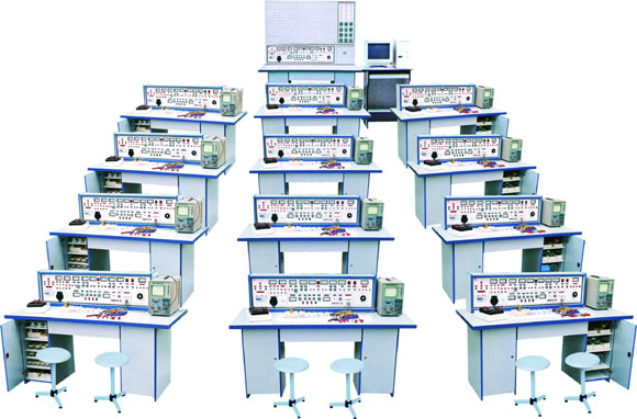
KRA-18A 通用电工实验室设备(多媒体电脑演示)
|
||||||||||||||||||||||||||||
KRA-18A GM electrician laboratory equipment (multimedia computer presentation)
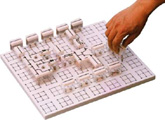
equipped with the most complete electrical and electronic equipment of the new product. Complete electrotechnics, electrical theory, experiment, and other electronic technology - Courses over 300 experiments, all the experimental devices have been installed in the box components, the components experiments abalone omnipotent box insert GM board, a flexible combination of experimental circuits, fight interpolation arbitrary. The same experiment with a variety of layout, and effectively improve the practical ability. Using transparent components box, the contents components can be clearly seen on the replacement of components can open the lid and maintenance convenience.
● Development of the purpose of this product: At present, the domestic types of schools electrician, electronic test equipment at most of the body, some schools in teaching demands made in various forms of experimental test-bed or box, because less processing by its own processing capacity constraints, processing crude, dysfunction, failed to meet the test requirements, personal and equipment also prone to accidents, and numerous experimental components to purchase, difficult to manage, it is difficult to test out the outline provisions experiment. Based on this, I learned German plant of similar products and the advantages of the domestic light of China's higher education, vocational education curriculum requirements developed this product. ● The product features: Experimental Taiwan has better security protection measures, more complete function (see test-bed structure profiles). Test-bed tables with a common central circuit board, board injection from the surface of containing abalone into a group of mutual Unicom jack, component box on arbitrary in its fight inserted into experimental circuits, components box box transparent, intuitive, and the lid will never fade bearing components symbols, lines clear aesthetic. Box with lid to use more scientific pressure style structure, maintenance removable convenience. Experimental components placed in a drawer about The above table, greatly improving the management level, the degree of planning, greatly reduce the teachers experimental preparations. ● scope of application: Apply to higher, intermediate, vocational school and technical school electrotechnics, electrical theory, experimental electronic technology, and other courses. AC-DC to be completed, the oscillation, magnetic circuit circuit operational amplifier, rectifier circuits, AC-DC amplification circuits, digital logic circuits, such as circuit experiment. The device is the upgrading of the existing laboratory equipment or newly built, expanded, the ideal laboratory products. It is equipped with the level of school, grade A an important indicator. The experimental reduced teacher preparations. Special configuration: One, electrical, electronic, electric tractors teachers teaching units equipped with a portable Development of a test box Second, experimental demonstration of a set of software and troubleshooting Third, the development of new electronic design experiments Training 1. Traffic lights at a crossroads 2. Responder design 3. The countdown timetable for the design calculation 4. Standard Clock Design 5. Mobile lamp design 6. Temperature frequency converter design 7. Brightness frequency converter design 8. Liquid Control Alarm 9. Function Generator Design 10. The four A / D converters
● three sets of laboratory equipment and the operation of test-bed structure of the same table: electrician, electronics, laboratory equipment, trailers and the operation of the test-bed structure of the same table)
L, test-bed shell specifications: 1230 × 350 × 200mm 2, three-phase insurance Block 3, 3-phase power input indicators 4, master switch: The power supply master switch, a belt containing leakage - 5, Test button: Test leakage switch leakage function 6, power input only instructions l 7, power output instructions three (red, green, yellow color) 8, AC voltage table: instructions output voltage line 9, voltage switch: the voltage used in conjunction with a table, showing supervisor Output voltage line with the size of symmetric situation 10, wiring Block 5: A three-phase four-unit output and ground wire L1, ammeter: W output phase current instructions 12, 4 sockets: A four-unit three-phase power supply output 13, wiring Block 2: B exchange low-voltage power supply unit output 14, and electricity meters (2A): B cell current exchange instructions 15, knobs: B modules 3-24 V voltage output options 16, Switches: C modules dual DC voltage regulator power switch 17, knobs: C modules dual Ⅰ Road steady flow conditioning 18, knobs: C II Road regulator modules dual regulation 19, wiring Block 2: C modules Ⅰ Road output DC voltage regulator 20, insurance Block: C dual voltage regulator power supply modules insurance 21, meters, 4: dual power supply voltage, current instructions 22, wiring Block: D unit output DC 5 V regulator 23, and electricity meters: D unit Current 0 5A output instructions 24, switch 1: control of the low-voltage alternating current, signal source 25, switch 2: E unit control AC-DC Power Surge 26, and electricity meters: E unit AC voltage output instructions 27, wiring Block 4: E unit exchanges, DC output 28, rotary button: E unit 0 a 240 V voltage regulator 29, socket: G Unit 220 V output sockets 30, rotary button: audio power amplifier volume adjustment 31, wiring Block 2: audio signal input 32, the button: single pulse so that it can switch 33, wiring Block 3: single pulse output 34, meters: sine wave function generator output voltage instructions 35, rotary button: sine wave output attenuation rate of coarse-3 36, rotary button: sine wave output to fine-tune the degree of convergence 37, wiring Block: sine wave output 38, rotary button: rectangular wave output rate regulation 39, wiring Block: triangular wave output 40, rotary button: function to fine-tune the frequency signal generator 41, wiring Block; Rectangular wave output 42, rotary button: function signal generator frequency rough-5 43, and electricity meters: Function Generator output frequency instructions 44, Multimeter: 500 45, experimental desktop size 1600 × 7O0mm 46 GM board: standard 350 × 900mm, components in the box Arbitrary fight inserted its experiment 47, storage plate: placing components Box 48, left store counters: placing storage plate (with locks) 49, drawer: place commonly used tools 50, and the right store counters: placing storage plate (with locks) 51, Oscilloscope: Open-type (user-owned) 52, tools ● test-bed main technical indicators: First, input power: three-phase four - Second, the output power and signal
L, A unit: three-phase four -
2, B modules: exchange 3,6,9,12,15,18,24 V 3, C modules: dual steady flow regulator power supply (with overload and short circuit protection), 2P output voltages are 0 to 30 V, The multi-turn potentiometer for conditioning, maximum current output for 2A. Voltage Stability: <10-2 load stability: <10-2 Ripple voltage: <5mV. 4, D unit: DC regulator 5 V, current 0.5 A 5, E modules: vertical flow adjustable voltage 0-240 V continuous current 2A 6, F modules: 220 V voltage outputs for external equipment use. Third, single-pulse sources: 1, each allocation of a button switches can be a positive and negative pulse output 4. Function signal generator (sine, triangle wave, rectangular wave) 1, the frequency range: 5 Hz一55 OKHz divided into five bands 2, the frequency of instruction: directly from the table to read out Hz 3, the output voltage range: sine wave: 5 Hz - 25OKH> 4.5V, 25OKHz - 55OKHz> 3.5V Three attenuation: Odb, 2Odh, 4Od with continuous fine-tune Rectangular wave: 5 Hz - 25OKHz> 4.5V, 25OHHz - 55OKHz> 3.55V, continuous adjustable rate Triangular wave: 5 Hz - 55OKHz> lV 5, audio power amplifier: Audio input voltage of not less than 10 mv output power of not less than 1 W, adjustable volume, with speakers, amplifier for amplifying circuit can also signal tracing equipment for use. 6, insulation resistance:> 5M Ω 7. Leakage protection: leakage current less than 30 mA action ● equipment structure, and with pilot projects First, structures and equipment (24 for example) (1), laboratory tables: 12 students experiment tables, the Set of two experimental tables external dimensions: 160 × 70 × 80cm. Table central configuration circuit board (size: 35 × 90cm), according to the experimental circuits on arbitrary in its fight boxes inserted into experimental circuit components. Components box transparent intuitive box, the contents components can be clearly seen lid and India have never faded components symbols, lines clear aesthetic, with the lid of the box using pressure card, maintenance removable convenience. Each experiment tables equipped with a rubber plate, the protection circuit board and general desktop (if required in the desktop placed Motor, welding, etc.). The table below is the storage component counters, placed experimental components. (2), showing the Taiwan table: 1 Taiwan teaching Taiwan tables, respectively control 12 students Taiwan tables of power. GM board legislation in the experimental demonstration of the stage screen, measuring 160 × 70cm. To explain, presentations. (C), experimental stations: A total of 13 units, students experiment tables and various teaching units equipped with a Taiwan table. (4), equipment with: 13 units three-phase motors, 26 hours relays, 26 thermal relays, 78 exchanges and contacts, 117 TAC DC Table, 13 multimeter, 13 sets of stripping wire pliers and top mouth pliers, screwdrivers and other tools, 13 sets of experiments necessary resistance, potentiometer, inductors , capacitors, transformers, magnets and other components unit strip box (component has been installed in the unit placed inside the box). (5), user-owned equipment: 1, oscilloscope (model limited) 2, transistors millivolt Table 3, Power Table 4, Waterloo line rheostat
Second, experimental projects
1, the use of Electrical Measurement Instrument 2, used the identification and detection devices 3, linear and nonlinear components of components voltammetry 4, the characteristics of the power supply 5, the potential value of the voltage value of 6, ammeter, and the expansion-Voltage Meter 7, Kirchhoff's law certification 8, holes mortem levy Lenz's Law 9, the principle of superposition and certification reciprocity theorem 10, Norton theorem Thevenin's theorem and the post-mortem levy 11, voltage and current source of the equivalent transformation 12, controlled source of research 13, a band circuit experiment 14, the Second Circuit transition process 15, Research LC components in the DC Circuit and the exchange of 16, was negative for the maximum power of the conditions 17, the measurement circuit parameters exchange 18, sine exchange RLC components in the circuit characteristics 19, RL and RC series circuit experiment 2 O, RLC series resonant circuit 21, fluorescent circuit connections and power factor improvement 22, the star of the load, 1.30 Next Act 23, the three-phase circuit and power measurement 24, R-C network of selected frequency 25, the Swiss population research network 26, single-phase transformer experiment 27, mutual inductance circuit experiment 28, the use of three-phase asynchronous motors with starter 29, 3-phase motor control relay contact with the basic circuit 30, a three-phase motor Y △ Starting Control Experiment 31, the order of three-phase motor control experiment 32, three-phase motors can rake Brake Control Experiment Use of these 32 experiments can be completed the following components circuit experiment 33, the simplest circuit 34, Circuit points potential and the choice of reference point 35, the series resistance 36, the parallel resistance 37, Resistance Hybrid 38, resistor divider circuits 39, the entire circuit Ohm's law 40, Bridge Application and balance conditions 41, node voltage Law 42, loop voltage Law 43, slip Current law 44, RCL parallel circuit 45, Series circuit 46, transformers structure and working principle 47, the first law Kirchhoff 48, Kirchhoff Second Law 49, fluorescent circuit principle 50, expanding voltage meter range 51, expanding range ammeter 52, RC circuit over the course 53, RL filtration process 54, the series circuit capacitance 55, capacitor parallel circuit 56, the charge and discharge capacitors 57, AC-DC capacitor in the role of 58, bar magnet coils in the campaign 59, capacitor Hybrid 60, pure resistance inductance, capacitance circuit 61, the magnetic coupling coil-Series 62, the magnetic coupling coil reverse Series 63, the working principle of Ohm Table 64, the double-switch control 65, with oscilloscope observed hysteresis loop 66, magnetic circuit Ohm's law 67, the two coils of the same name - and mutual inductance 68, mutual inductance coupling 69, improve power factor method 70, single-phase power measurement circuit 71, and hand power circuit 72, filter circuit 73, the relationship between resistance and temperature: measured filament voltammetry The different voltage resistance. 74, three-phase induction motor control switch is to experiment 75, a slightly Overload Protection of the Line of Control 76, the button negative to the positive control of the control circuit 77, contactor control of a triangular buck Star starter control circuit |


