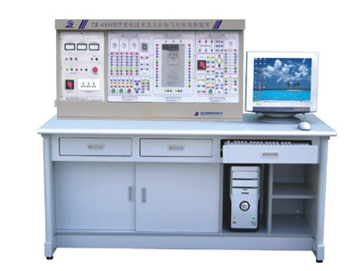
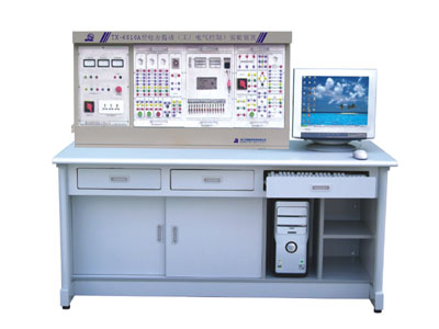
KRJ - 6860E variable frequency technology and industrial electrical control devices Training

The device combines current colleges "electric drive", "Frequency Control Technology", and so on experimental program requirements, in particular applies to the institutions of the existing laboratory equipment upgrading. The device fully cultivate the actual practical ability of students to complete more engineering professional courses such as "electric drive", "variable frequency control technology" experiment, and expansion "PLC programmable technology" "DC motor" such courses experiment.
Main features:
1, the five-wire three-phase power input, the power switch control from leakage protection, a three-phase ceramic fuse.
2, the power control screen for exigency stop by the exigency stop button control.
3, the screen is equipped with a voltage leakage protection devices, or control screen if it has strong power output leakage phenomenon, and to cut off the power, indeed
Bao experimental process safety.
4, Ping tops of a set of current leakage protection, control screen if leakage phenomenon, leakage current over a certain value, that is cut off
Power.
5, experimental use of closed cable sheathing structure, the use of safe, reliable, to prevent electrocutions.
Device configuration:
First, power control screen
And the three-phase 380 V single-phase 220 V AC power, providing the necessary experiments DC Power Supply (0-30 V/1.5A), automatic transmission and automatic protection and restoration of function, a current-mode and dual-voltage leakage protection.
Second, experimental tables
Experiment tables for steel and wood structure, desktop as fire, flood, wear resistant plate, solid structure, modeling aesthetic generous.
Three experimental components linked Box
1, relay contacts control
Provide AC contactor (coil voltage 380 V), thermal relays, electronic-time relays, trip switches, lights, the band Electric button Fuse. Panel Painting a device's shape, and all the work of terminal devices primer on the panel, wiring for experimental use, contactors and relays state of the work has lights instructions.
2, Box pegged Frequency Technology Experiment
Inverter with advanced vector control, constant torque function, instructions rich, powerful, operation is simple and convenient, with Rs485 communication interface. Converter boxes will be linked wiring terminal leads to the panel, experimental convenient and flexible.
3, 3-phase asynchronous motors
4, experimental links, the experimental guidance
The main technical parameters:
1, input supply: AC380V ± 5% (five three-phase line) 50 HZ;
2, unit power consumption: <1 KW
3, ambient temperature: -5 ° C -40 ° C
4, relative humidity: ≤ 85% (25 ° C)
5, inverter hardware: FR-A40 - 0.4KW-CH (R)
6, appearance size: 1600 X700X1450 (mm)
Training projects:
(1) Frequency Control Technology
1, the basic operation of inverter
2, the composition and procedures inverter operation
3, the inverter frequency hopping speed of the operation and functioning of multi -
4, the panel set up and operation of functional parameters Training
5, external analog converter open-loop speed control Training
7, the open-loop system
8, the closed-loop system
9, and running with operation
10, communications operation functioning
11, the instantaneous power failure starter
12, PID control system
13, inverter configuration
(B) Electrical Control Technology:
1, low-voltage electrical Recognition
2, AC-DC voltage relay voltage tuning
3, the use of universal switch
4, low-voltage electrical options
5, in accordance with electrical equipment mapping electrical wiring diagram
6, the basic control circuit wiring practice
7, three-phase squirrel cage induction motor of the work
8, the start-up of three-phase asynchronous motors with speed control
9, the resistance of single-phase induction motor starter
10, single-phase induction motor capacitor Starter
11, moving to the single-phase induction motor capacitor
12, two-speed asynchronous motor
13, three-phase asynchronous generator
14, to move the three-phase asynchronous motor control circuit and self-locking
15, the three-phase asynchronous motor control circuit is to reverse
16, and from the workstations automatic control circuit
17, the sequence control circuits
18, the two control lines
19, the three-phase squirrel cage induction motor control circuit buck Starter
20, Wound Three-phase asynchronous motor starter control circuit
21, two-speed asynchronous motor control circuit
22, C620 Lathe Electric Control
23, M7130 Surface Grinder electrical control circuit
24, electric hoist the electrical control circuit
25, X62W milling machine control circuit simulation analysis Debugging
Training materials Matching (optional)
1, the DC motor pegged box experiment
2, DC Motor
3, PLC programmable logic controller box pegged

SHANGHAI KERONG TEACHING APPARATUS CO.,LTD
 English Tel: +86.21-56301098 Fax: +86.21-66613899
QQ: MSN:
MSN: shkr123@hotmail.com
Website: www.shkr.com Email: kerong@shkr.com
 English Tel: +86.21-56301098 Fax: +86.21-66613899
QQ:
 MSN:
MSN: shkr123@hotmail.com
Website: www.shkr.com Email: kerong@shkr.com


