
Assessment training rooms of Electrical and Electronic Equipment, Electronic & Electrical Equipment appraisal training rooms
KRA-09C Vertical Universal Electronic Laboratory complete sets of equipment
KRA-09D Vertical Electrical and Electronic Power Drive Lab General complete sets of equipment (triple)
KRA-09E Vertical General Electric and Electronic electric drive laboratory (with a DC machine) Quad Play
Use, characteristics:
The device according to the latest curriculum development of the State Education Commission, is the most technologically advanced and equipped with electrical and electronic equipment electric drag the most complete new product. To complete electrical engineering, electrical theory, electronics, electric drive control circuit, DC motor start, speed control, reverse, brake test more than 400 types of courses such as electrical experiments, all the experimental components have been installed in the component box on the experiment, the component box into common porous universal board, test the circuit combination of spirit, fight insert arbitrary. The same experiment with a variety of layouts, to effectively improve their practical ability. Component boxes with transparent body, built-in components at a glance, the replacement component may put the lid open, easy maintenance.
2, Structure and equipment
First, test-bed tables: see color pictures, one two, tables, Dimension: 160 × 70 × 8Ocm. Central configuration tables, general-purpose circuit boards. Tables, each equipped with a rubber sheet to protect the general-purpose circuit board and the desktop (if required in its place electrical, welding, etc.). Components are stored under the tables, cabinets, placing components.
Second, test-bed: General electrical and electronic laboratory equipment based on the increase in speed links, Ia, If showing link. Student Teaching Test-bed tables and tables, each equipped with one.
Third, teaching stations: a Taiwan teaching units, respectively, the power control 12 sets of students, common circuit board legislation in the experimental stage, screen presentation, size 150 × 7Ocm, devoted to lectures, presentations.
4, the equipment is equipped with: 26 sets three-phase motor 180W, 13 units DC motor 200W, 52 just be relays, 26 time relay, AC contactor 91, 156 AC and DC tables, 13 MF500 multimeter, 39 indicator, 42 trip switch, control buttons 78, 13 inverted cis switch, 26 transformers, 13 three-phase double-cast Knife, 13 three-phase Knife, 13 sets of experiments in resistor, potentiometer, inductor coil , mutual inductance coil, diode, transistor, FET, integrated, SCR, logic-level switch, logic-level components such as box directions (components have been installed in the device box), 13 sets of stripping pliers, screwdriver, beak pliers and other tools.
5, assessment function: Equipment used to set board and troubleshooting faults the method of separating plates to facilitate the evaluation operation. Equipped with a timer and alarm equipment misoperation recorder, usually used as a clock with alarm timer time set up an experiment in advance to remind the power supply after the power cut off. It also has a number of times automatically record a misoperation. Skills assessment test for students to provide a uniform standard. Security features: fitted with current-type, voltage-leakage protection device; over-current protection devices. If leakage, over-current or short circuit, the system alarms and cut off power supply to ensure the overall safety of persons and equipment. Students apply to the special requirements of operation.
6, a user-owned equipment:
Oscilloscope (model not limited to), the transistor millivoltmeter Power Meter
Note: Students Number of seats may be increased or decreased according to requirements of schools.
3, experimental projects:
1, electrical pilot project
1, the use of electrical measuring instruments
2, the identification and detection of common components
3, linear components and nonlinear volt-ampere characteristics of components
4, the power of the external characteristics of
5, potential value, voltage value of the determination of
6, ammeter and voltage meter expansion process
7, Kirchhoff's Law verification
8, verify that Lenz's law
9, superposition principle and validation of Reciprocity Theorem
10, Thevenin's theorem and Norton's theorem verification
11, voltage source and current source of the equivalent transformation
12 characteristics of controlled source
13, a first-order circuit experiment
14, second-order circuit transition process
15 to study the LC components in DC and AC circuit characteristics
16, the load conditions for maximum power
17, AC Measurement of circuit parameters
18, sinusoidal AC circuit characteristics of RLC components
19, RL and RC series circuit experiment
2O, RLC series resonant circuit
21, fluorescent lamp circuit connection and power factor improvement
22, compared with the load of the star, Triangle Connection
23, three-phase circuits and power measurement
24, R-C network of frequency-selective
25, 2 Swiss population NETWORK
26, single-phase transformer test
27, mutual inductance circuit experiment
28, using the three-phase asynchronous motor starter
29, three-phase motor control, basic circuit of relay contacts
30, three-phase Y-△ starter motor control experiment
31, the order of three-phase motor control experiment
32, three-phase motors can rake brake control experiment
32 experiments using the above components are to be completed by the following circuit experiment
33, the most simple circuit
34, the circuit potential of the CPC Central Committee General Office and the reference point of all points, the choice of
35, resistor in series
36, the parallel resistance
37, resistance of the hybrid
38, resistor voltage divider circuit 39, the whole circuit Ohm's law
40, the bridge application and equilibrium condition
41, node-voltage method
42, loop voltage method
43, branch current method
44, RCL parallel circuit
45, series circuit
46, transformer structure and working principle of
47, Kirchhoff's first law
48, Kirchhoff's Second Law
49, fluorescent lamp circuit principle
50, expand the range voltmeter
51, expanding current meter range
52, RC circuit over the course
53, RL filtration processes
54, capacitor series circuit
55, capacitance of the parallel circuit
56, capacitor charging and discharging
57, capacitors in the AC and DC role
58, a bar magnet in the coil of the movement
59, capacitor hybrid
60, a pure resistance, inductance, capacitance circuit
61, magnetic coupling coil Shun string
62, magnetic coupling coil of the Cross-Dressing
63, Ohm meter works
64, double-switch to control two
65, with the oscilloscope observation of hysteresis loop
66, magnetic circuit Ohm's law
67, two coil mutual inductance and the end of the same name
68, mutual inductance coupling
69, increase the power factor method
70, single-phase power measurement circuit
71, recorder power supply circuit
72, filter circuit
73, the relationship between resistance and temperature: The voltammetry measured filament resistance at different voltages.
74, three-phase induction motor control is transferred experimental Knife
75, with overload protection control line slightly
76, the button control, positive inversion control circuit
77, contactor control a triangle buck Star starter control circuit
3, electronic pilot projects
1, crystal diode characteristics and detection
2, input-output characteristics of transistor
3, low-frequency small-signal voltage amplifier
4, direct-coupled two-stage amplifier
5, RC-coupled two-stage amplifier has been
6, negative feedback amplifier performance of
7, transformers strokes combined push-pull power amplifier
8, complementary symmetry push-pull power amplifier (OTL)
9, single-phase half-wave rectifier
10, single-phase full-wave rectifier
11, single-phase bridge rectifier
12, single-phase bridge rectifier filter
13, single-junction transistor characteristics
I4, single-junction transistor trigger circuit
15, a simple test and thyristor controlled rectifier
16, FET test
17, Series Voltage Regulator
18, Differential Amplifier Circuit
19, integrated op-amp parameters of the test
20, integrated circuit op-amp into law
21, integrated op-amp adder circuit
22, integrated op-amp integrator
23, integrated circuit op amp differential
24, integrated op-amp sine wave oscillator Venturi
25, capacitance three-point oscillator
26, inductive three-point oscillator
27, integrated circuit regulator
28, no steady-state circuit (multivibrator)
29, Schmitt trigger
30, integrated with the gate logic function test
31, integrated circuit logic gate non-functional test
32, integrated circuit logic OR gate shake function test
33, integration and functional testing of non-gate logic ibo
34, CMOS gate test
35, the basic RS flip-flop
36, JK flip-flop
37, D flip-flop
38,555 time-base circuit applications (square wave generator)
39, Er Yishi binary counter
40, Er Yishi binary decoder 8421
41, adder 42, subtracter
43, with the integrated and non-gate structure Shu monostable flip-flop
44, combinational logic circuit
44 experiments using the above components are to be completed by the following experiment
45, P-N junction electrical properties of one-way
46, 3 possession kBo measurement circuit
47, the measurement circuit transistor IcBo
48, the three powers current amplification tube
49, the VA characteristics of triode
50, with a load of single-stage small-signal voltage amplification
51, voltage negative feedback bias circuit
52, partial pressure type current negative feedback bias circuit
53, with a stable operating point thermistor
54, with a stable operating point diode
55, analysis of the low-frequency characteristics of Ce
56, common base amplification circuit
57, a total of collector amplification circuit
58, common source of basic amplifier circuit
59, FET self-bias amplifier circuit
60, partial pressure of type FET self-bias circuit
61, a total drain FET circuit
62, a total gate field effect transistor circuits
63, single-tube resistance-capacitance amplifier
64, the basic DC-amplifier circuit
65, with the resistance of the emitter potential of the upgraded class
66, with ear-pressure level was raised emitter-bit
67, transformer-coupled amplifier circuit
68, A power amplifier circuit
69, B power amplifier circuit
70, series current negative feedback
71, series voltage feedback circuit of poverty
72, parallel voltage negative feedback circuit
73, parallel current negative feedback circuit
74, 2 in the negative feedback amplifier circuit
75, emitter output circuit
76, bootstrap emitter output circuit
77, with the attenuation of high-frequency capacitance-voltage
78, with negative feedback to eliminate self-excited oscillation
79, the battery monitoring circuit
80, composed of FET transistor amplifier circuit
81, PNP-NPN direct-coupled amplifier circuit
82, common base common-emitter amplifier circuit
84, level photoelectric control
85, a simple temperature control circuit
86, analog circuit automatic street light control summary
87, RC phase-shift oscillator
88, pairs of T frequency-selective network
89, pairs of T consisting of oscillator frequency-selective network
90, transformer feedback oscillation circuit
91, transformer feedback FET oscillator circuit
92, anti-theft alarm circuit
93, series crystal oscillator circuit
94, complementary audio oscillator News Xiangqi
95, police News Xiangqi
96, musical doorbell circuit
97, the electronic alarm circuit
98, the basic form of the differential amplifier circuit
99, electronic doorbell circuit
100, quasi-complementary symmetry circuit
10I, 3 OTL complementary symmetry circuit
102, tail-differential amplifier circuit
103, differential input single-ended output
104, single-ended input double-ended output
105, single-ended-input single-ended output
106, dual power-type long-tailed differential amplifier circuit
107, differential amplifier experimental circuit
108, with a constant current source of differential amplifier circuit measures
109, single-ended output differential amplifier circuit analysis of the temperature drift
110, Flasher circuit
111, shipped the amplifier's basic access method
112, the current differential op amp used for the exchange of scaling up
113, Vos A simple measurement method
114, Ios simple measurement method
115, Aod simple measurement method
116, common-mode rejection ratio Cmrr Simple Test
117, maximum common-mode input UIcm the number of simple test operation circuits
118, Yopp A simple test
119, SR measurements
120, the basic in-phase amplification Connection
121, consisting of LC oscillator op amp
122, Electric Cup thermostat circuit
123, cited to the reverse-side input-zero measure
124, cited to the same type to the end of zero means the Shi
125, for the power value of the access will not be too large Selection of Circuit
126, the use of transistor base current to achieve
127, increase the use of T-network equivalent feedback resistor
128, so that complementary work in class AB tube expansion
129, on the capacitor when the measures for correcting the negative wear
130, inverting input protection measures
131, with the phase input protection measures
132, the use of Zener protection device
133, take the wrong power supply polarity protection
134, power up transient over-voltage protection
135, diode detector circuit
136, the use of PN junction temperature coefficient measurement of temperature
137, double-diode limiter
138, inverting op amp basic circuit
139, Variable scaling
140, with the phase of basic op amp circuit
141, voltage / current conversion circuit
142, current / voltage conversion circuit
143, the voltage follower
144, Differential Amplifier Basic Circuit
145, op amp's differential input
146, inverting input summation operation
147, with the phase input summation operation
148, double-ended input summation operation
149, the basic integral circuit
150, EG exam leakage swear filter circuit of the integral operation
151, improve the integration time constant
152, Fast integral circuit
153, a first-order differential equation analog circuit
154, analog circuitry second-order differential equations
155, the basic differential circuit
156, utility differential circuit
157, using the indirect method are similar to differential
158, the basic operation circuits on the number of
159, the use of transistor characteristics of the logarithm of the composition of the
160, against the number of basic circuit amplification
161, Vo is proportional to the circuit VxVy
162, a simple zero-crossing over the circuit of this
163, compared with hysteresis characteristics of the circuit circuitous
164, compared with the circuit of this double-limit
165, Tri-State Comparison of dual-limit circuit
166, using a limit of detection rate of two tubes
167, minimum inspection rate selection circuit
168, the basic sampling protection circuit
169, RC passive network-end low-pass filter circuit
170, filter circuit receiving the component input with the phase
171, filter circuit components of the inverting input received
172, a simple second-order RC filter circuit
173, a typical RC active filter circuit
174, two-stage active filter circuit
175, 2 multi-channel feedback active filter circuit
176, a typical second-order high-pass active filter circuits
177, the basic band-pass filter circuit
178, a typical band-pass filter circuit
179, with double-T network consisting of band-stop filter Lu
180, the inverter output limiter
181, practical difference between the op-amp
182, rectangular wave root Dang Lu
183, resistance-capacitance phase-shift trigger circuit
184, electric mattress thermostat device
185, the width of the rectangular wave generator with adjustable
186, a simple sawtooth wave generator
187, amplitude-frequency adjustable sawtooth wave generator
188, single-phase bridge rectifier circuit commonly used method of painting
189, the largest full-wave rectifier circuit reverse peak voltage
190, capacitor filter circuit
191, capacitor filter with a resistive load
192, full-wave rectifier capacitor filter circuit
193, RC filter circuit
194, multi-stage RC filter circuit
195, the basic LC filter circuit
196, T-type filter circuit
197, twice the voltage rectifier circuit
198, three times the voltage rectifier
199, the basic voltage regulator tube voltage regulator circuit
200, the basic adjustment of tube voltage regulator circuit
201, with a larger part of the regulator circuit
202, adjust the tube steady flow circuit
203, e-filter
204, series regulator circuit
205, shunt regulator circuit
206, e-hypnotic device
2O7, three-terminal regulator integrated circuits
208, is the power output of adjustable voltage regulator integrated circuits
209, single-phase full-wave controlled rectifier
210, silicon ear-pressure spike voltage circuit
211, single-phase half-wave controlled rectifier
212, single-phase half-controlled rectifier bridge
213, charging rejection silicon rectifier theory
214, the impact of perceptual load on the SCR
215, thyristor trigger turn-on test
216, back-EMF load thyristor circuit
217, simple electronic voltage regulation circuit
218, Test UJT divider ratio
219, unijunction oscillator circuit
220, unijunction trigger the application circuit
221, diodes "and" gate
222, transistor, "or" gate
223, and logic visualization
224, or logical visualization
225, non-logical visualization
226, triode "non" door
227, triode "and not" gate.
228, triode "or" door
229, 3 pull tube bistable circuit
230, 3 Maple tube monostable circuit
231, Transistor Multivibrator
232, Chi-bit trigger circuit
233, emitter-coupled bistable
234, symmetric multivibrator
235, ring multivibrator
236, differential-type one-shot circuit
237, integrated circuit Schmitt
238, rectangular wave generator
239, single-pulse circuit
240, continuous pulse generator
3, power drag, DC motor pilot project
1, knife switch is to switch control circuit
2, contactor control circuit Jog Forward
3, with a positive self-locking switch control circuit
4, has been looking for a positive transfer control circuit protection
5, inverted cis-positive inversion control circuit switch control
6, contactor control circuit interlocking positive inversion
7, buttons chain of positive inversion control circuit
8, buttons, complex interlocking contactor control circuit
9, automatic round trip control circuit
10, contactor control blood pressure starting line of a little series resistance
11, time relay control of blood pressure control circuit series resistance
12, Manual Y / △ starter Buck
13, contactor control Y / △ starter Buck
14, time relay control Y / △ buck starting 15, QX3-13 Type Y / △ automatic starting control circuit
16, half-wave rectifier power brake control circuit
17, full-wave rectifier power brake control circuit
18, C620 lathe electrical control circuit
19, manual step-down start
20, single-phase operation reverse brake control circuit
21, electric hoist electric control circuit
22, C6163 lathe electrical control circuit
23, control circuit interlocking control circuit
24, the main circuit interlock control circuit
25, DC motor to start
26, DC motor speed control
27, DC motor reversal
28, DC Braking Experiment 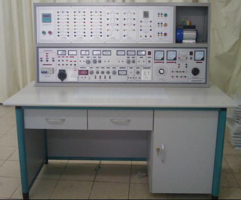
SHANGHAI KERONG TEACHING APPARATUS CO.,LTD
电工电子考核实训室设备、电子电工考核实训室设备  English Tel: +86.21-56301098 Fax: +86.21-66613899
QQ: MSN:
MSN: shkr123@hotmail.com
Website: www.shkr.com Email: kerong@shkr.com